This section of Electronics engineering Multiple Choice Questions and Answers (MCQs) focuses on the “ Operational Amplifier(OP-AMP) and its application as an adder, integrator, differentiator, etc. ”. These MCQs are very helpful for the preparation of University exams, Engineering exams, and various Technical competitive exams. It is advised that before solving these MCQs one must have a basic understanding of opamp. CLICK HERE to learn the basics of Opamp.
ELECTRONICS – OPERATIONAL AMPLIFIER (OPAMP) MCQs
1. The output of an integrator is given as:
Explanation:-Integrator is a circuit in which output voltage waveform is the integral of the input voltage waveform and is given as V_O\;=-\frac1{RC}\int_0^tV_{in}\operatorname dt
2. If the output of opamp changes by 30 V in 6 µs then the slew rate is :
Explanation:- slew rate is defined as the maximum rate of change of output with respect to time. Its unit is V/µs, so SR\;={\left.\frac{dv_o}{dt}\right|}_{max}
3. If the common mode gain is 0.27 and diffrential voltage gain is 2700, the CMRR is:
Explanation:- CMRR is defined as the ratio of differential voltage gain (Ad)to the common-mode gain (Ac)
so , CMRR =Ad/Ac =2700/0.27 = 10000
CMRR in dB = 20log10CMRR = 20log1010000= 80dB.
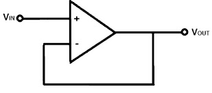
4. Identify the given circuit:
Explanation:-The given circuit is a noninverting amplifier with Rf= 0 and Ri= ∞ .
So output voltage Vo=(1+Rf/Ri)Vi= (1+ 0/∞)Vi =Vi
since output voltage is same as the input voltage and also gain is equal to 1 ,that’s why this circuit is called a voltage follower 0r unity gain amplifier. As it only provides a means of isolating an input signal from a load ,so it is also known as a Buffer amplifier
5. The bandwidth of an ideal opamp is:
Explanation:- The bandwidth of an ideal opamp should be infinite, so that any frequency signal ranging from o to ∞ Hz may be amplified without any attenuation.
6. An opamp has a feedback resistance RF=20kΩ and the resistance in the input side on inverting terminals are R1=20kΩ, R2=10kΩ, R3=5kΩ. The corresponding inputs are Vi1= +8V , Vi2= -2V , Vi3= +1V. The non-inverting terminal is grounded then the output voltage is:
Explanation:- When all inputs are applied on the same terminal of opamp then the circuit act as an adder. So the output of the adder is given as
Vo= -RF[Vi1/R1 + Vi2/R2 + Vi3/R3]=-20[+8/20 + (-2)/10 +1/5]= -8V.
7. In an opamp used as a differentiator R=1MΩ and C=2µF. If a signal Vi=2sin2000πt mV is used as input voltage then the output voltage is:
Explanation:- The output equation of differentiator is given as
Vo= -RC d(vi)/dt = -1×106 x 2×10-6d(2sin2000πt)/dt= – 8000π cos2000πt mV = – 8π cos2000πt V
8. Opamp amplifies the difference between the voltages applied at the non-inverting input and inverting input.
Explanation:- Opamp amplifies the difference between the two input voltages applied at the non-inverting and inverting terminals. It does not amplify the input voltages themselves.
9. The number of pin in 741 opamp IC is:
Explanation:- The 741 op-amp IC has 8 pins. The function of each pin is listed below:
Pin 1: offset null
Pin 2:Inverting Input
Pin 3:Non-inverting Input
Pin 4:Negative power supply(V-)
Pin 5:offset null
Pin 6:output
Pin 7:positive power supply(V+)
Pin 8:No connection(NC)
10. The input and output resistance of an ideal opamp is :
Explanation:- In an ideal opamp:
(i)Differential voltage gain, input resistance, slew rate, and CMRR are equal to infinity
(ii))Output resistance, Common mode voltage gain, offset voltage, and power supply rejection ratio(PSRR)are equal to zero.
More Related MCQs
- ELECTRONICS ENGINEERING – SEMICONDUCTOR DIODE MCQs
- ELECTRONICS ENGINEERING – SEMICONDUCTOR MATERIALS MCQs
- CONTROL SYSTEM – POLAR AND NYQUIST PLOT MCQs
- CONTROL SYSTEM – BODE PLOT MCQs
- CONTROL SYSTEM – GAIN MARGIN AND PHASE MARGIN MCQs
- CONTROL SYSTEM – ROOT LOCUS TECHNIQUE MCQs
- CONTROL SYSTEM – STATE SPACE ANALYSIS MCQs
- CONTROL SYSTEM – ROUTH HURWITZ CRITERION MCQs
- CONTROL SYSTEM – STEADY STATE ERROR MCQs
- CONTROL SYSTEM- TIME DOMAIN ANALYSIS MCQs
- CONTROL SYSTEM – SIGNAL FLOW GRAPH MCQs
- CONTROL SYSTEM – BLOCK DIAGRAM MCQ
- CONTROL SYSTEM – BASICS OF CONTROL SYSTEM MCQs


Fantastic website. A lot of helpful information here. I am sending it to a
few friends ans also sharing in delicious. And obviously, thanks to your effort!