This section of Control Systems Multiple Choice Questions and Answers (MCQs) focuses on the ” Signal Flow graph”.It will help you to prepare for various competitive exams.
CONTROL SYSTEM – SIGNAL FLOW GRAPH MCQs
1. The node that has one or more incoming branches only is called as:
Explanation:- Sink node or output node: It is a node that has one or more incoming branches only and no outgoing branches.
Source node or input node: It is a node that has only outgoing branches and no incoming branches.
2. Signal flow graph (SFG) is applicable to Nonlinear systems:
Explanation:- Signal flow graph (SFG) is applicable only to linear time-invariant (LTI) systems.
3. The node having both incoming and outgoing branches is called as:
Explanation:- Chain node: It is a node that has both incoming and outgoing branches.
Sink node or output node: It is a node that has one or more incoming branches only and has no outgoing branches.
Source node or input node : It is a node that has only outgoing branches and no incoming branches.
4. The transfer function of the signal flow graph given below is :
Explanation:- The overall transfer function of SFG is obtained by using Mason’s gain formula.Here in given figure, forward path gain g1=10 and loop gain L1=0.5 , Δ1 =1 and Δ=1-L1 = 1-0.5 , according to Mason’s gain formula TF = (g1 .Δ1)/Δ = 10/1-0.5 =20
5.The combinations of two non touching loops in the given signal flow graph are:
Explanation:- There are 5 individual loops in the given SFG. These are L1= -G1H1 , L2= -G3H3. , L3= -G1G2G3H2 , L4= -G4H4 , L5= -G5H5 .Also, there are 5 combinations of two non touching loops and these are (i) L1L2 (ii) L1L5 (iii) L1.L4 (iv) L2L5. (v) L3L5
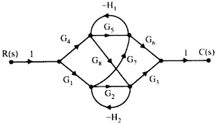
6.How many forward paths are there in the given signal flow graph?
Explanation:- In the given figure there are 6 forward paths i.e g1.=G2G2G3 , g2= G4G5G6 , g3=G1G7G6 g4=G4G8G3 , g5= -G4G8H2G7G6, g6=-G1G7H1G8G3
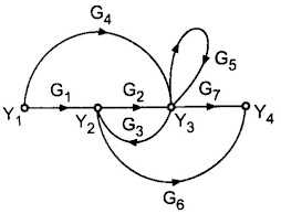
7. The number of forward path and individual loops in the signal flow diagram given below are:
Explanation:- It has 4 forward paths g1= G1G2G7 , g2=G4G7 , g3=G1G6 , g4=G4G3G6 and has 2 individual loops L1= G2G3 , L2=G5.
8. Signal flow graph is used to find:
Explanation:-Signal flow graph is used for obtaining the transfer function of the system by using Mason’s gain formula.
9. Which of the following is not a true statement for the signal flow graph?
Explaination:- In the signal flow graph, nodes are arranged from left to right in a sequence.
10. The number of combination of three non touching loops in the given signal flow graph is:
Explanation:- There are no combinations of three non touching loops in the given signal flow graph.
More Related MCQ’s

