1. The point at which the same signal can be applied to two or more systems as input is known as :
Explanation:- Takeoff is the point from where we can apply the same signal as an input to two or more than two systems.
2. When three blocks having transfer function G1(s), G2(S), G3(s) respectively are cascaded then the overall transfer function is given as:
Explanation:- In cascaded connection, all the blocks are connected in series and the transfer function of each block gets multiplied by each other to get the overall transfer function of cascaded connection.
3.The pictorial representation in a short form of the cause and impact relationship between the input and output of any physical system is known as:
Explanation:-Block diagram is a pictorial representation of a system that gives the relationship between the input and output of a physical system.
4. The over all transfer function of a positive unity feed back closed loop control system is :
Explanation:- The overall transfer function of a positive feedback control system is G(s)/1-H(s)G(s) and here in the question positive unity feed closed-loop system is given so put H(s)=1 and we get G(s)/1-G(s) as an overall transfer function.
5. The direction of flow of signal from output to input is known as :
Explanation:- In forward path, the direction of flow of signal is from input to output while in the feedback path the direction of flow of signal is from output to input.
6. Feedback control system is considered as:
Explanation:- the feedback control system is basically a low pass filter.
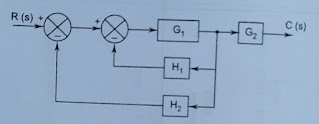
7. The overall transfer function of the given block diagram is:
Explanation:- In this figure, H1 and H2 are connected in parallel so it becomes H1+H2 and then a feedback loop is formed which is solved and the transfer function of this loop becomes G1 /(1+G1(H1+H2)) and then it is cascaded with G2 and both transfer function get multiplied due to series connection and becomes (G1.G2)/(1+G1(H1+H2)).
8. When two blocks having transfer functions G1(s) and G2(S) are connected in parallel then the overall transfer function is :
Explanation:- When blocks are connected in parallel then their transfer function gets added to each other.
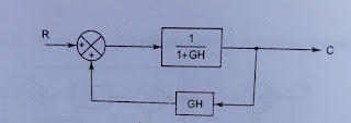
9. The transfer function of the given close loop control system is :
Explanation:- The positive feedback close loop system with G as forward path gain and H as feedback path gain has a transfer function as G/1-GH . In the given question the forward path gain is 1/1+GH and the feed path gain is GH so put these values in the positive feedback transfer function formula and after solving it we get 1.
10. By introducing negative feedback in the system,its stability is………. and gain is……..:
Explanation:- Due to negative feedback of a system,its gain reduces and stability increases.
More Related MCQ’s


