Table of Contents
Definition of Zener Diode
Zener diode is a reverse-biased heavily doped P-N junction diode that operates in the breakdown region.
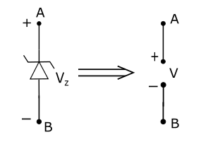
Symbol of Zener Diode

Biasing Of Zener Diode
(I) Forward Bias
When the anode of the Zener diode is connected to the positive terminal and the cathode is connected to the negative terminal of the battery then the diode is said to be forward-biased and behaves as the normal forward bias P-N junction Diode as shown in fig below:


Reverse Biasing Of Zener Diode
When the cathode of the Zener diode is connected to the positive terminal and Anode is connected to the negative terminal of the battery then the diode is said to be reverse biased. Zener Diode in Reverse bias condition act as a voltage regulator.
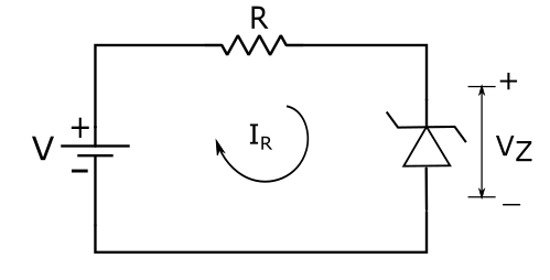
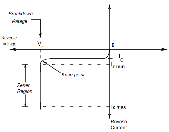
As we increase the reverse bias, initially a very small reverse current will flow but at a certain reverse voltage the reverse current rises sharply and that voltage is called breakdown Voltage or Zener Voltage and is denoted By Vz and the diode is said to be in Zener region where the Zener voltage remains constant but current changes depending upon the applied voltage.
Complete V-I Characteristic of Zener Diode.

Equivalent circuit of Zener Diode
The practical Zener diode is equivalent to a battery of voltage Vz in series with a resistance rz , Resistance rz is known as the dynamic resistance of the Zener diode given as
r_z\;=\frac{\triangle V_z}{\triangle I_z}

In the ideal equivalent circuit of the Zener diode, the value of Zener resistance rz is zero. During the voltage from 0 V to Vz in reverse bias, the Zener diode behaves as an open circuit as shown in 9. The Zener diode is said to be “ON” when the reverse bias voltage exceeds Vz as shown in fig 8 while it remains “OFF” if the voltage across the Zener is less than Vz in reverse bias. The “ON” & “OFF” states are shown below:

Zener Diode application as a Shunt regulator /Voltage regulator.
A voltage regulator is a circuit whose function is to maintain a constant output d.c voltage in spite of the a.c input voltage fluctuations or changes in load resistance values.
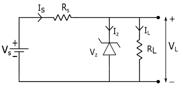
The input current is calculated by
{\displaystyle V_s\;=I_s\;R_s\;+\;V_z}
{\displaystyle I_s\;=\frac{V_s\;-V_z}{R_s}}
Here V_s= Input d.c unregulated voltage
V_z= Voltage across Zener diode.
The load Voltage is
V_L=V_z
Working of Zener diode Shunt regulator
(I) Regulation with varying Load
In this case, the load resistance RL is fixed and the input voltage Vs is varied as shown in fig below:

The output VL =Vz is a constant
{\displaystyle I_L\;=\;\frac{V_L}{R_L}=\;\frac{V_z}{R_L}} = Constant
and {\displaystyle I_s\;=\;I_z\;+\;I_L}
Now if Vs increases then total current Is increases. Hence the current Iz increases to keep IL constant. If Vs decreases then total current Is decreases. Hence the current Iz decreases to keep IL constant.
(ii) Regulation with Varying Load
In this case, the input voltage is constant and the load resistance RL is varied.

As Vs is constant so the total current Is will also be constant.
Since , Is = Iz +IL = constant
Now if RL decreases, So IL increases, and Iz decreases to keep IR constant. Similarly if RL increases. so IL decreases and Iz increases to keep IR constant. Therefore the load voltage remains constant.
VL = Constant
Advantages of Zener diode voltage regulator
- It is a simple circuit
- It is more reliable
- It provides regulation over a wide range of current.
- It is smaller, lighter, and more rugged.
- It has a longer life.
- It is cheaper.
The disadvantage of the Zener Voltage Regulator
- This voltage regulator cannot be made adjustable.
- Due to large changes in the load current, large power wastage occurs.
- The output voltage varies slightly due to Zener impedance rz.
- Large power gets dissipated in the series resistance Rs.
- The output volatge cannot be chosen independently but depends upon the breakdown voltage of the Zener diode.
Application of Zener diode
- Zener diode is used as a voltage regulator.
- It is used as a peak clipper
- It is used as meter protection against damage from accidental application.
- It is used for switching operations.
- It is used as a reference voltage for comparing other voltages against it.
Comaprision of zener diode and P-N junction diode
| ZENER DIODE | P-N JUNCTION DIODE |
|---|---|
| 1. It operates in reverse bias condition. | 1. It operates in Forward bias condition. |
| 2. It has a high doping level. | 2. It has a low doping level. |
| 3. Dynamic Zener resistance is very small in reverse breakdown conditions. | 3. The diode resistance in reverse-biased conditions is very high. |
| 4. It allows the current to flow in both the direction i.e forward and reverse direction. | 4. It allows the current to flow only in one direction i.e in forward direction. |
| 5. It does not obey ohm’s law. | 5. It obeys Ohm’s law. |
| 6. Its breakdown voltage is higher than normal on the junction diode. | 6. Its breakdown voltage is comparatively lower than the Zener diode. |
| 7. At high reverse voltage Zener diode does not get damaged. | 7. At high reverse voltage P-n junction diode can get damaged |
| 8. Application of Zener diode are Voltage Regulator, peak Clipper, Protection Circuits, Reference Voltage, etc. | 8. Application of P-N junction diode are Rectifiers, Voltage Multipliers, Clippers, Clampers, etc. |
Suggested Article from Wisdom Imbibe: