Table of Contents
Digital Voltmeter (DVM)
Definition
A digital voltmeter is a device that is capable of displaying the measured value of A.C or D.C voltage as discrete numerals instead of pointer deflections on a continuous scale as in analog instruments. The main work of DVM is to calculate voltage between two points.
Block diagram of DVM

The block diagram of the digital Voltmeter consists of three stages:
- Signal preparation.
- Analog to digital conversion.
- Display Unit.
The signal preparation stage modifies the signal amplitude according to the requirement. Here, the resistive attenuator is used to decrease the large incoming signal, and an amplifier is used to amplify the small incoming signal to the measurable range.
Types of Digital Voltmeter
- Ramp type Digital Voltmeter
- Integrating or Dual slope DVM
- Potentiometer type DVM.
Working of Digital Voltmeter
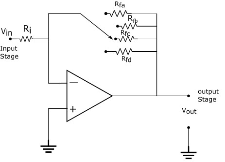
The input circuit for DVM using an operational amplifier is shown below in fig 2 below:

The opamp is a multi-stage integrated circuit. Amplification is controlled with negative feedback. Since amplifier gain, ‘A’ is proportional to the ratio of the feedback and input resistance.
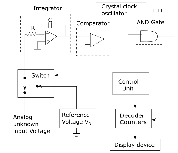
{\displaystyle A= -\frac{R_f}{R_i}}In the next two stage, the analog input signals are typically converted into digital signals in the form of binary or BCD data and suitably display in the display unit. The block diagram of the dual slope A/D converter with display unit is shown in fig 3.

The unknown input voltage Vin that is to be calculated is given to the input of the integrator via a selection switch for a known time period T. The output of the integrator is given by the equation,
{\displaystyle V_c\;=-\frac{V_{in}}{RC}T}Here R & C are the resistance and capacitance values in the integrator.
The output from the integrator is compared with zero volts reference in the comparator, the output from the comparator will be a positive voltage for the entire period T, the one input of AND gate is high so the output of AND gate is the same as the second input i.e it passes the clock pulse generated by crystal clock oscillator and is counted in the counter during this period.

At the end of the known time period ‘T’, the counters are reset by the control circuit and at the same time it activates the selection switch so that the negative known reference voltage VR is applied to the input of the integrator as shown in fig 4, the output from the integrator will be a positive going ramp given by the equation,
{\displaystyle V_c\;=\frac{V_R}{RC}t}
At the end of the time period t, Vc is equal to zero volts. All this time, the counter is counting, and hence ‘t’ can be known. Since the integrator output begins at zero volts, integrates down to -Vc, and then integrates back up to zero volts, So the two equation be equated as
{\displaystyle \frac{V_{in}}{RC}T\;=\frac{V_R}{RC}t}{\displaystyle \frac{V_{in}}{\cancel{RC}}T\;=\frac{V_R}{\cancel{RC}}t}{\displaystyle V_{in}=\frac{V_R}Tt}
Since the values of T and VR are already known. So the unknown input voltage Vin is directly proportional to the time t, that is the content of the counter. Hence T, VR, and t are known then unknown input voltage can be calculated.
Merits of DVM
The merits of DVM over other voltmeter types are as under:
- It has greater speed.
- It has higher accuracy & resolution.
- No parallex error
- Reduced Human Error
- It has compatibility with other digital equipment for further processing and recording.
Demerits of DVM
- The speed of operation of DVM is limited due to digitizing of the circuit.
- Digital voltmeters providing some extra features are expensive.
Digital Multimeter(DMM)
Definition
The digital multimeter is an electronic device that can measure a.c & d.c voltages, a.c & d.c currents, and resistances over several ranges.
Block diagram of DMM
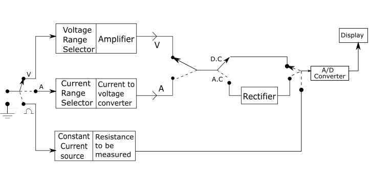
The basic circuit of the digital multimeter is always a d.c voltmeter as shown in fig

Measurement of various quantities by DMM:
- Measurement of Voltage.
- Measurement of current.
- Measurement of resistance.
Measurement of Voltage
Since ADC can process a voltage only in its specified range. So the voltage divider circuit is used for selecting the voltage range to be measured and if it is A.C voltage then it is first rectified before supplying to the ADC.
Measurement of current
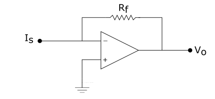
A series of current sensing resistors are used to measure either d.c or a.c current, the unknown current that needs to be measured is passed through one of the current sensing resistors used as the feedback resistance of an OPAM, and the voltages developed across the resistor is digitized by the DMM.

The current to voltage converter output voltage is given as
{\displaystyle V_o=-I_sR_f}Where Rf is the known resistance. The output voltage Vo which is proportional to the unknown source current Is is applied to the DVM section of DMM and the value of current Is is displayed.
Measurement of resistance
The DMM measures the resistance by applying a known current from an internal current source to the unknown resistance and then digitizes the resulting voltage developed.

The scale changer circuit output can be given as
{\displaystyle V_o=-\frac{R_f}{R_i}V_i}Where input voltage (Vi ) and resistance (Ri) are the known values, the output voltage(Vo) which is directly proportional to the unknown resistance Rf is applied to the DVM section of DMM, and the unknown resistance Rf value is displayed.
Application of Digital Multimeter
- DMM is used for checking circuit continuity.
- For measuring d.c voltage across various resistors and electronic circuits.
- For measuring a.c voltages across power supply transformer.
Merits of Digital Multimeter
- DMM alone can perform various measuring functions.
- It is easily portable due to its small size and light weight.
- It can make measurements with reasonable accuracy.
Demerits of Digital Multimeter
- It is a costly instrument
- It cannot make precise and accurate measurements due to the loading effect.
- Technical skill is required to handle it.
More Related articles

