Table of Contents
Cathode Ray Oscilloscope (CRO)
CRO Definition
The cathode ray oscilloscope is a device used for studying wave shape of alternating current and voltages as well as for measurement of voltage, current, power, and frequency.
Block diagram of CRO

The block diagram of CRO consists of the following major systems:
Cathode Ray Tube
It generates the electron beam, accelerates the Beam to a high velocity, deflects the beam to create the image, and at the end, it contains a phosphor screen where the electron beam strikes and becomes visible.
Vertical amplifier
It amplifies the signal waveform to be viewed so that a high-intensity input signal is applied at the vertical deflecting plate to create a bright
Horizontal amplifier
Sawtooth voltage is fed in the horizontal amplifier which is then applied to horizontal deflection plates. The horizontal deflection plates deflect the beam along the horizontal direction which is useful to create the waveform along with the time domain.
Sweep generator
It generates a sawtooth voltage waveform used for the electron beam’s horizontal deflection.
Trigger Circuit
It generates trigger pulses to start the horizontal sweep.
High and Low Voltage supply
The power supply block provides the voltage required by the cathode ray tube to generate and accelerate the beam as well as to supply the required operating voltage for the other circuits of the oscilloscope. The cathode-ray tube requires high voltages while the electron gun & other circuits of CRO needs low voltages.
Delay Line
A delay line is always included in the vertical amplifier of High-Frequency oscilloscopes. The purpose of such lines is to delay the vertical signal enough to keep it from reaching the CRT deflection plate before the horizontal sweep circuit is running.
Cathode Ray Tube
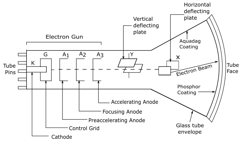
The main part of the Cathode ray Oscilloscope (CRO) is the Cathode ray tube (CRT), with some extra circuitry to operate it. CRT consists of the following parts:
- Electron gun Assembly
- Deflection Plate Assembly
- Screen for CRT
- Glass body
Electron Gun Assembly
The electron gun assembly consists of an indirectly heated cathode, a control grid surrounding the cathode, a pre-accelerating anode(A1), Focusing Anode(A2) & an accelerating Anode(A3). The function of the Assembly is to provide a focused electron beam that is accelerated toward the phosphor screen.
(i) Cathode
The cathode is a nickel cylinder on which an oxide of barium is coated and when it gets heated emits plenty of electrons. The surface of the cathode from where it emits electrons should be as small as possible like a point.
(ii) Control Grid
The control grid is made up of metal and has a cylindrical shape that is covered at one end but has a small hole in the cover. The purpose of a small hole in the grid is to provide a path for electrons through it and concentrate the electron beam along the axis of the tube.
(iii) Focusing and accelerating anode
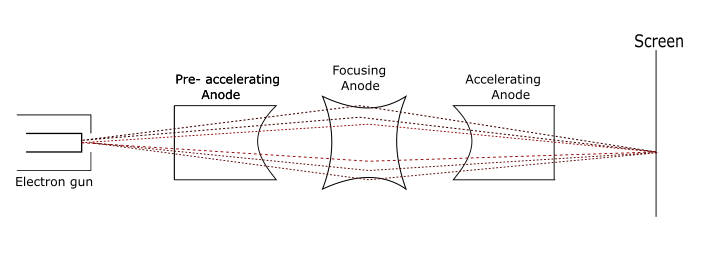
Through a small hole present in the control grid, the Electron beam comes out and enters a pre-accelerating anode that is a hollow cylindrical in shape with a voltage of a few hundred volts more positive than the cathode due to which the electron beam gets accelerated. The electron beam is then focused & accelerated towards the screen by focusing on the anode & accelerating the anode.
Deflecting plate Assembly
The electron beam after leaving the electron gun assembly travels through two pairs of deflection plates. One pair of plates is mounted horizontally and produces vertical deflection & is called a Vertical deflection plate or Y plate. The other pair of plates are mounted vertically and produce a horizontal deflection. This pair of plates is known as Horizontal deflection plates or X plates.
(i) Vertical (Y) deflection system
The signal to be examined are applied to the vertical (Y) deflection plates.
(ii) Horizontal (X) deflection system
The horizontal or X deflection plates are fed by a sweep Voltage that produces the time base as shown below:

When the sweep voltage is at its negative peak then the electron is on the leftmost side of the screen, when the sweep voltage becomes zero the electron moves towards the center of the screen and when the sweep voltage is at a positive peak then the electron moves towards the rightmost side of the screen. This process continues as long as sweep voltage is fed to the horizontal deflecting plates and a horizontal line that acts as a time base for the input signal to be viewed on-screen.
Screen for CRT
The end wall of the CRT called the screen is coated with phosphor when struck by high-energy electrons, it glows.
Glass body
The glass body is funnel-shaped having a phosphor-coated screen at its end. The inner wall of CRT between the neck & screen is coated with a conducting material known as aquadag. This coating performs two functions:
(i) The electron beam gets accelerated after it passes between the deflecting plates.
(ii) It collects the electrons produced by secondary emission when an electron beam strikes the screen.
Application of CRO
- Tracing of an actual waveform of voltage or current.
- Measurement of Capacitance and Inductance.
- Comparison of phase and frequency.
- In television
- In Radar
- For tracing transistor curves.
- For engine pressure analysis.
Lissajous Figure/ Patterns
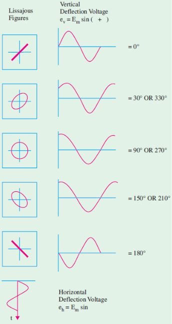
When two sine waves are applied simultaneously to the horizontal and vertical deflection plates of C.R.O then the image formed on the screen of the CRO is known as the Lissajous figure.
When the phase difference between two sinusoidal signals is 0° or 180° then a straight line is displayed on the screen of the CRO, for 90° phase difference a circle is formed and for any other phase difference an ellipse is formed as shown below in figure
Measurement of Electrical Quantities with CRO.
Measurement of Frequency of a Voltage signal.
The Lissajous pattern is of two types:
- Closed Lissajous pattern and has no free ends.
- Open Lissajous pattern and has free ends.
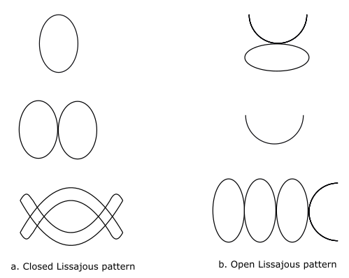
In Lissajous pattern
{\displaystyle \frac{f_y}{f_x}\;=\frac{Positive\;Y-Peak\;in\;pattern}{Positive\;X-Peak\;in\;pattern}}
Where , fy is frequency of Vertical signal
fx is frequency of horizontal signal
{\displaystyle \frac{Point\;of\;Tangency\;to\;a\;vertical\;line}{Point\;of\;Tangency\;to\;a\;horizontal\;line}\;=\frac{\omega_x}{\omega_y}=\frac{f_x}{f_y}}
Measurement of phase difference.
Let there be two sinusoidal voltage signals as
{\displaystyle v_h=\;V_h\;\sin\omega t}
{\displaystyle v_v=\;V_v\;\sin(\omega t+\varnothing)}
Where ∅ is the phase difference
Since deflection is directly proportional to the amplitude of voltage. So,
{\displaystyle d_h=\;D_h\;\sin\omega t}
{\displaystyle d_v=\;D_v\;\sin(\omega t+\varnothing)}
At time t=0 , Value of dv and dh are dvo = D sin ∅ and dho = 0
{\displaystyle Sin\varnothing\;=\frac{dv_o}{D_v}}
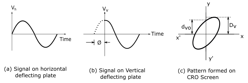
Fig 6. Measurement of phase difference
Voltage Measurement(Amplitude Measurement)
CRO can be used for peak to peak or peak voltage measurement as shown in fig below
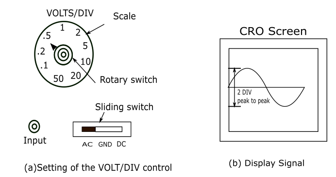
Voltage Measurement procedure
- Count the number of divisions in the vertical direction which corresponds to the peak to peak value. 1div = 1 cm
- Then read the position of VOLTS/ DIV control. In fig (7) VOLT/DIV control is on 1V/DIV.
- Calculate the peak-to-peak voltage
{\displaystyle peak\;to\;peak\;Voltage\;=(2\;DIV)\;\times\;(1\;VOLT/DIV)=2\;VOLTs}<br>
{\displaystyle RMS\;value\;of\;the\;voltage\;=\;\frac{Peak\;to\;peak\;voltage}{\sqrt[2]2}=\;0.707\;V}
Current Measurement
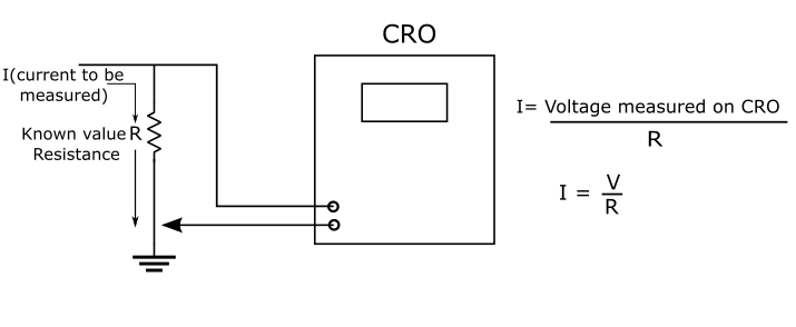
A CRO can measure only voltage. It cannot measure current directly. Therefore, first, the current to be measured is passed through a resistance R of Known value. The voltage developed across this resistor is measured on the CRO.
More Related articles

