
Table of Contents
Logic Gate
A logic gate is the most basic digital circuit that is used to perform logical operations on binary inputs. It can have many inputs but a single output.
There are 3 basic gates:
- OR Gate
- AND Gate
- NOT Gate
There are two Universal Gates:
- NAND Gate
- NOR Gate
There are two Derived Gates:
- Ex-OR Gate
- Ex-NOR Gate
Basic Gates
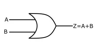
OR Gate
The OR is used to perform the Logical addition operation also known as OR function. Let A and B are two independent variables. If the OR operation of A and B is Z then,
Z = A+B
Where A and B are the input variables and Z is the output Variable.
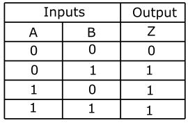
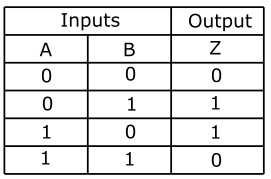
The truth table of OR Gate is shown below:
Important OR Operation
The important points to remember regarding OR gate & OR operation are:
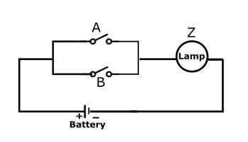
- The OR gate produces output 1 when any of the input variables is 1.
- The OR gate produces output 0 when all the input variable is 0.
- With the OR operation, 1+1=1, 1+1+1+1+……………= 1 and so on.
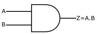
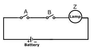
AND Gate
The AND gate is used to perform the logical multiplication, also known as AND function. The AND gate can have more than two inputs but a single output.
Z = A.B
Where A and B are the input variables and Z is the output Variable.
The AND GateTruh table is shown below:
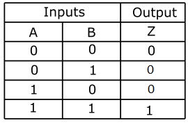
Important AND Operation
The important points to remember regarding AND gate & AND operation are:
- The AND operation is performed exactly like ordinary multiplication of 1s and 0s.
- An output of the AND gate is equal to 1 only if all the inputs are 1.
- The output of AND gate is 0 if any of the input is 0.
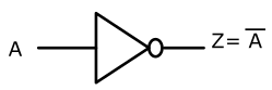
NOT Gate or Inverter
The NOT Gate also known as Inverter is used for the operation of inversion or complementation. This means that an inverter or Not gate changes High(1) to Low(0) and Low(0) to High(1) . NOT gate is the only gate that has only one input and one output.
The logical equation for a NOT gate is

Where A is the input variable and Z is the output variable.

The NOT gate Truth table is drawn below:

Universal Gates
There are two Universal Gates:
- NAND Gate
- NOR Gate
NAND and NOR gate are also known as Universal gates because they can be used individually as the universal building blocks to build any logic circuit. Also the logic circuit. Also the logic functions like AND , OR ,NOT etc can be easily constructed using only NAND or NOR gates. Further, any boolean expression can be implemented either by the use of NAND gates only or NOR gates only.
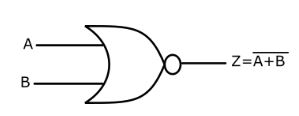
NOR gates
The word NOR implies an OR function with an inverted output. The output of a NOR gate is high (1) only if all inputs are L.ow(0). The output logic equation of NOR Gate is given as

where A and B are input Variables and Z is the output variable.
The NOR gate Truth table is drawn below:

Construction of AND , OR , NOT gate by NOR Gate
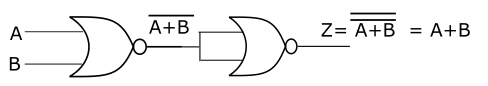
(i) OR gate by NOR Gate
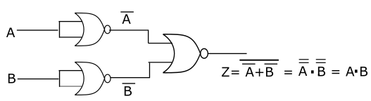
(ii) AND gate by NOR gate
(iii) NOT gate by NOR Gate

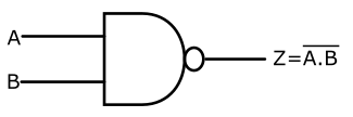
NAND Gate
The word NAND implies an AND function with an inverted output. The output of a NAND gate is Low(0) only if all the inputs are high(1). The logic equation of the NAND gate is

where A & B are input variables and Z is the output variable
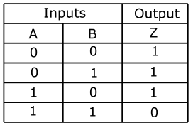
The NAND GateTruth Table is shown below:
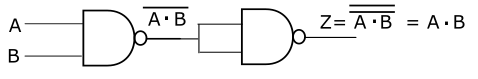
Design of AND , OR and NOT gate by NAND gates only
(i) AND Gate by NAND Gate
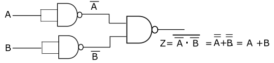
(ii) OR Gate by NAND Gate
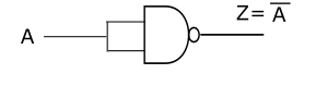
(iii) NOT Gate by NAND Gate
Derived Gates
Exclusive OR gate (EX-OR Gate)
The output of EXOR gate is high only if both inputs are different. The output is Low if both inputs are same i.e. either both inputs are 1 or both are 0. The output logical equation of the EX-OR gate is

Where A & B are input variables and Z is output Variable.

The truth Table of EX-OR Gate is shown below:
Exclusive -NOR Gate( EX-NOR Gate)
The output of the EX-NOR gate is high if both the inputs are same. The output is low if both inputs are different. The logical equation of the EX-NOR gate is


The truth Table of EX-NOR gate is shown below:

Recommended Articles