
Objective
To simulate a simple LED Blinking circuit using Tinkercad, demonstrating the fundamental concept of digital output control with Arduino. The project will turn an LED ON and OFF at 1-second intervals using an Arduino Uno.
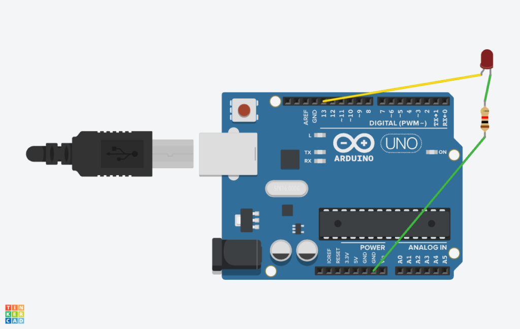
Circuit

Procedure
Step 1: Open Tinkercad and Create a New Circuit
- Go to Tinkercad.
- Sign in or create a new account.
- Click on “Circuits” and then “Create a new Circuit”.
Step 2: Add Components to the Workspace
- In the components panel, search for and drag the following items onto the workspace:
- Arduino Uno
- LED (Light Emitting Diode)
- Resistor (220Ω)
- Breadboard (optional but recommended)
Step 3: Connect the Circuit
- Connect the LED:
- Anode (+, longer leg) → Connect to pin 13 on the Arduino.
- Cathode (-, shorter leg) → Connect to one side of the 220Ω resistor.
- Other side of the resistor → Connect to GND (Ground) on Arduino.
- Your circuit is now complete!
Step 4: Write the LED Blinking Code
- Click on the “Code” button (or “Blocks + Text” and switch to “Text” mode).
Step 5: Simulate the LED Blinking
- Click the “Start Simulation” button.
- Observe the LED:
- It should turn ON for 1 second.
- Then turn OFF for 1 second.
- The cycle repeats indefinitely.
Code
| void setup() { pinMode(13, OUTPUT); // Set pin 13 as an output } void loop() { digitalWrite(13, HIGH); // Turn LED ON delay(1000); // Wait for 1 second digitalWrite(13, LOW); // Turn LED OFF delay(1000); // Wait for 1 second } |
Program Logic And Explanation
This Arduino program controls an LED by making it blink ON and OFF every 1 second using digital output.
Program Logic:
- Setup the LED pin → Configure pin 13 as an output in setup().
- Turn LED ON → Set pin 13 to HIGH (5V) using digitalWrite(13, HIGH);.
- Wait for 1 second → Use delay(1000); to hold the LED in the ON state.
- Turn LED OFF → Set pin 13 to LOW (0V) using digitalWrite(13, LOW);.
- Wait for 1 second → Use delay(1000); to hold the LED in the OFF state.
- Repeat the cycle infinitely → Since loop() runs continuously, the LED blinks forever.
Code Explanation:
1. void setup() – Runs Once at the Start
| void setup() { pinMode(13, OUTPUT); // Set pin 13 as an output } |
- setup() is executed once when the Arduino starts.
- pinMode(13, OUTPUT); sets pin 13 as an output pin, allowing it to control an LED.
2. void loop() – Runs Continuously
| void loop() { digitalWrite(13, HIGH); // Turn LED ON delay(1000); // Wait for 1 second digitalWrite(13, LOW); // Turn LED OFF delay(1000); // Wait for 1 second } |
- loop() runs forever, executing the instructions inside it in sequence.
- digitalWrite(13, HIGH); sets pin 13 to HIGH (5V) → LED turns ON.
- delay(1000); makes the program pause for 1 second.
- digitalWrite(13, LOW); sets pin 13 to LOW (0V) → LED turns OFF.
- delay(1000); makes the program pause for another 1 second before restarting the cycle.
Output
- The LED connected to pin 13 will turn ON for 1 second, then turn OFF for 1 second, repeating forever.